Product code : 90-1088
Category : Soil Strength (Triaxial) Sub Category : Triaxial System
Product Group : Triaxial System
| Type | Product Name | Product Code | Standard Code | |
|---|---|---|---|---|
| NA | ||||
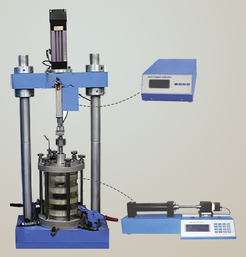
ELE Dynamic Electromechanical Triaxial Testing System is a triaxial system, based on an axially-stiff load frame with a beam mounted electro- mechanical actuator. It has been designed to fulfil the demand within the geotechnical laboratory testing industry for a lower cost, more basic dynamic triaxial testing system
This system superseded systems using pneumatic actuators in terms of life costs and overall usable performance. Electro-mechanical systems can carry out full load dynamic testing to the stated frequency. Electro-mechanical systems are environmentally friendly as they only draw the energy required to do the test, resulting in lower life costs. Electro- mechanical systems are also safer to run due to no high pressure air or hydraulic pipelines being required.
Triaxial Cell
• Conforms to IS:2720 (Part 11) & (Part 12) standards.
• Made from corrosion-resistant material with acrylic plastic cell cylinders.
• High-pressure capacity with reinforcement bands for applications up to 20 bar.
• Multiple take-off positions for cell pressure, pore water pressure, drainage, or back pressure.
Pressure Volume (PV) Controller
• Pressure Control Range: 0-1000 kPa with 1 kPa resolution.
• Volume Capacity: 200 cc with 1 mm³ resolution.
• Operational Modes: Standalone or computer- controlled.
• Precision Measurement: Includes highaccuracy pressure and volume control for soil mechanics laboratories.
| System consist of following elements | Data Acquisition System |
| • Load frame | ELE DAQ provides 4 channels of ultra-high resolution |
| • Triaxial cell | 24-bit having 500 samples per second. |
| • PV controller | A standard USB Interface provides direct PC connectivity and |
| • Data Acquisition system | is fully supported by the Test Software allowing |
| • DAQ software | Seamless integration into new and existing test setups |
| Technical Specification |
|
| Connection to PC | USB |
| Acquisition Channels | 4 Analogue + 1 Quadrature Decoder |
| Control Channels | 1 Analogue |
| Multi Box Capability | x4 |
| Max Number of Channels | Up to 16 analogue + 4 quadrature channels with synchronised data acquisition |
| Sample Rate | 500Hz |
| Resolution | 24 bit, 16,777,216 |
| Gain Ranges | 8 (preconfigured at factory) |
| Description | Enterprise level solution for dynamic acquisition and control |
| Voltage Resolution | ~ 0.000001 mVolts (1 nanovolt) |
| Voltage Input Type | Fully Differential, Balanced Precision Inputs with Integrated Signal Conditioning |
| Transducer Excitation Voltage | Differential, Fixed Precision +/-5V, Independent (not Ganged), Ratiometric Excitation |
| Number of Input Ranges | Pre-Configured Single Fixed Gain per Channel. Each channel can be individually customized at the factory to meet application requirements from +/- 10mV to +/- 10V. Standard setup is 1 channel +/-10V, 2 channels +/- 200mV, 1 channel +/- 30mV |
| Excitation Fault Tolerance | Independent Per Channel, if any channel is shorted the other channels will continue to operate normally |
| Current Input Mode | Yes- Via resistor fitted in cable termination (different ranges possible) |
| Differential Measurement Range | -10mV…+10mV to -10V…+10V for balanced differentialsignals |
| Transducer Calibration | Linear |
| Data Acquisition Options | Digital filtering for noise reduction |
| Digital Control | 500 Hz 32-bit floating point control loop |
| Analogue Contro | Support for Analogue motor drives only |
| Compliance Estimation | Set by user |
| Adaptive Control | Cycle-by-Cycle Reference Adaptation |
| Custom Waveforms | Repetitive custom waveforms with 256 points per cycle. Waveform streaming direct from file. |
